Loop by Loop: A Cold-Start Thermal Check for Wet Underfloor Heating
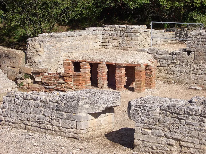
Photo: Allie_Caulfield Camera location43° 46′ 22.74″ N, 4° 50′ 02.5″ E View this and other nearby images on: OpenStreetMap 43.772984; 4.834027, CC BY 2.0, via Wikimedia Commons
The manifold is the least theatrical part of a wet underfloor heating system. It sits in a cupboard, a utility room or a purpose-made cabinet, and it does very little that is visible. Yet it holds the evidence. When a UK home reports that one room “never really gets warm” or that a kitchen floor is pleasant while a hallway floor is merely not cold, the manifold and the floor above it are usually telling the same story at different speeds.
A thermal camera is well suited to reading that story, but only if it is used as a sequence rather than a snapshot. A single warm patch on a floor is not proof of balance. It may be proof of a short loop, a thin screed, a sunny patch, a rug that has been moved, or a pipe that happens to sit close to the surface. The useful question is not “where is the warm patch?” but “how does each loop behave over time, relative to the others?”
Why a Cold Start Tells More Than a Warm Floor
Underfloor heating is a low-temperature, high-mass system. In a well-insulated UK home it may run at 35–45°C flow temperature, sometimes lower with weather compensation, and it relies on a large area of floor to release heat gently. That makes it slow. It also makes steady-state thermal images less informative than they appear. Once the floor has been warm for hours, many faults are hidden by the sheer spread of heat through the screed.
A cold start is more revealing. With the heating off for several hours, the floor becomes a relatively uniform baseline. When the system is then run with a known flow temperature and all relevant zones open, the rate at which each loop’s floor area warms becomes a diagnostic signal. Loops that receive flow, sit under a suitable covering and have adequate pipe spacing will rise together, within a few degrees of one another. A loop that lags, or one that races ahead, is worth investigating.
This does not require laboratory conditions. It requires consistency: the same camera, the same emissivity setting, the same viewing angle and the same measurement points, repeated at sensible intervals.
Set the Scene Before Pointing the Camera
Before the heating is switched on, record the baseline. Take thermal images of each room from a fixed position, ideally marked on a sketch plan. Note the floor covering, the approximate pipe spacing if known, and any rugs, furniture or mats that could affect surface temperature. In a UK November, avoid surveying immediately after direct sunlight has fallen on a floor, and avoid reading through low-angle reflections from windows or glossy tiles.
Camera settings matter. Most floor coverings — tile, engineered oak, vinyl, carpet — have reasonably high emissivity, but polished or metallic surfaces can mislead. If the camera allows it, set emissivity to a sensible value for the material and keep it constant across the sequence. Use a contact thermometer to validate a few surface readings. The camera is a mapping tool, not a substitute for a calibrated probe.
Read the Manifold Before the Floor
The manifold provides the context that the camera cannot. Record the flow rate on each loop if flow meters are fitted, the position of balancing valves, the pump setting and the flow and return temperatures. Note whether actuators are fitted and whether they are open. If the system has zoning, ensure the zone schedules are calling for heat in all areas being surveyed, or record which zones are active.
A loop with a low flow rate may still warm its floor, but it will usually do so more slowly. A loop with no flow may show a faint warm trace near the manifold and little elsewhere. An actuator that has failed closed may look identical to a closed balancing valve from the floor surface alone. The manifold narrows the possibilities before the camera is asked to confirm them.
The Sequence: What a Balanced System Looks Like
A useful sequence might run for 60–90 minutes, with images taken every 10–15 minutes, followed by a further reading after two or three hours. In a balanced system, the floor areas served by different loops should begin to rise at broadly similar rates. They will not be identical. Loop length, pipe spacing, screed depth and floor covering all introduce legitimate variation. A bathroom with tiles over a thin screed may respond faster than a living room with engineered oak over a deeper build-up. The pattern, not the absolute temperature, is the evidence.
A single warm patch is therefore never enough. If one area is warm while the rest is cool, the question is whether that area is simply responding faster, whether it is served by a short loop, or whether other loops are not receiving flow at all. The sequence distinguishes between these possibilities.
When a Loop Lags: Flow, Air, Actuator or Covering
A lagging loop is the most common finding. Check the obvious causes in order. Is the flow meter showing movement? Is the actuator open, and can it be manually overridden? Is the balancing valve open? Has the loop been properly commissioned? Air locks and kinked pipes are less common in a mature installation but not unknown. A blocked strainer or a failing pump can affect several loops at once.
The floor covering is a frequent confounder. Carpet and underlay slow the release of heat, so a carpeted room may read cooler at the surface even when the loop is performing correctly. A rug placed over a warm floor will produce a cool patch that is not a fault. Always map the floor as it is used, but interpret it with the covering in mind.
Actuators and Schedules: The Control Layer
Modern underfloor heating is rarely just pipework. It is a control system. Zone schedules can call different areas at different times, and a thermal survey conducted while some zones are off will show an imbalance that is really a scheduling decision. For a balance check, run all relevant zones together under a fixed flow temperature, then repeat under normal schedules if needed.
Actuators are a common failure point. A wax actuator that no longer extends, or a motorised head that has lost its signal, can leave a loop closed while the rest of the system runs. The thermal camera will show the result, but the manifold and the control panel explain it. Check the actuator position indicator, if fitted, and test manual override before concluding that the pipework is at fault.
Turning Evidence into Adjustment
Balance adjustments should be small and documented. If a loop is running too warm relative to the others, its balancing valve may be closed slightly; if it is lagging, confirm flow first. After each adjustment, allow the system to settle and repeat the thermal sequence. Avoid chasing identical surface temperatures. The aim is a coherent pattern of warming that matches the design and the room’s use.
A thermal survey of underfloor heating is not a one-off performance. It is a comparison over time. The manifold’s confession is slow, but it is legible to anyone who records the baseline, reads the flow rates and watches the floor rise loop by loop. The warm patch is only the beginning of the question.